Saturday, January 10, 2015

Gloucester Rocker Part 6 - More planking

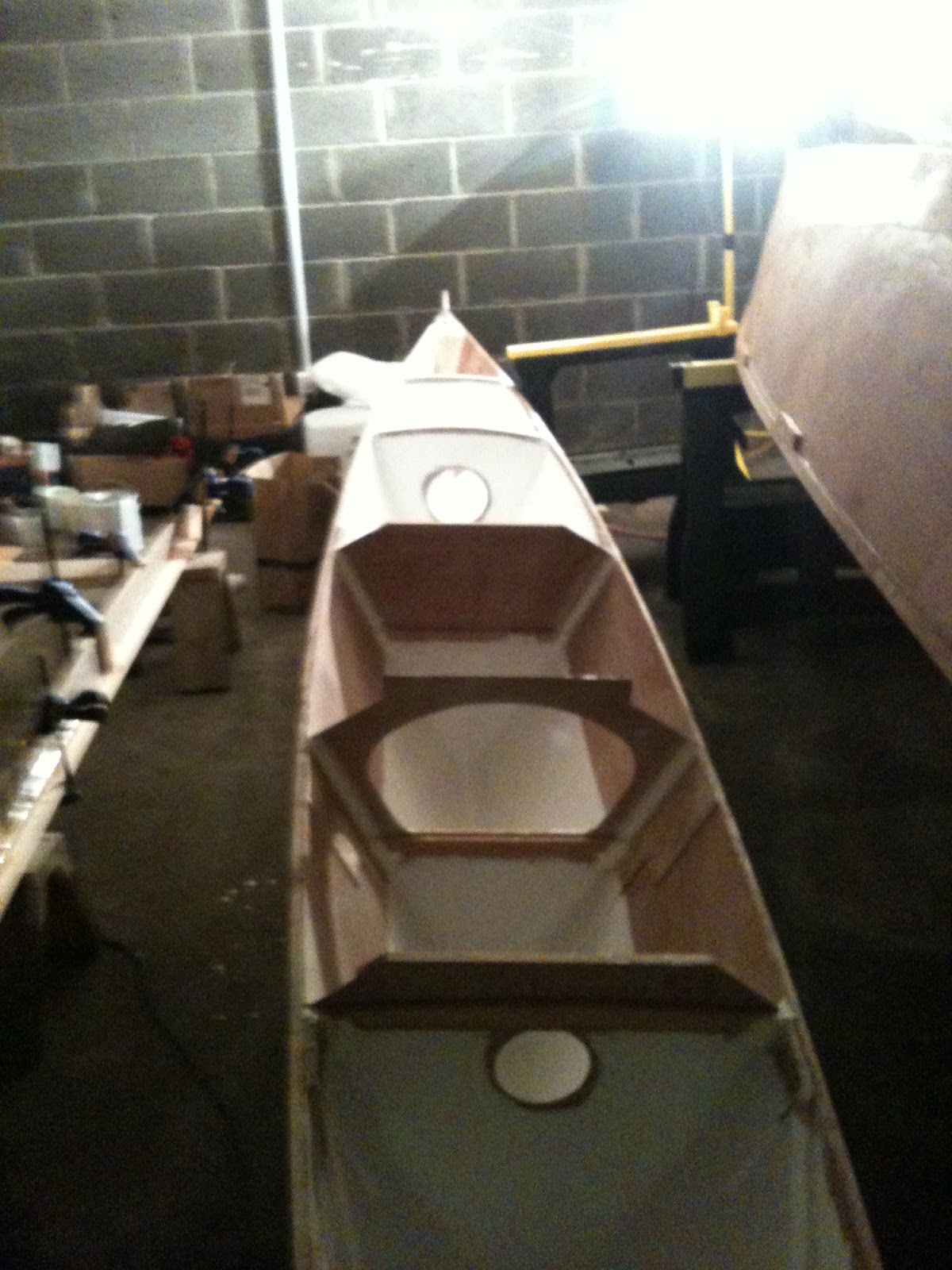
Fortunately there aren't that many planks to fit and it now goes pretty quickly. Two more planks on the starboard side:


Then two more on the port side:


Same view at the transom:


I love the way lapstrake planking make the shape of a boat pop!

Wednesday, January 7, 2015

Gloucester Rocker Part 5 - Cutting the Dory Lap bevels between planks

Now the hard/fun part, cutting the rolling 'dory lap' bevels. I have no idea if this is the right way to do these, but it was what worked for me and by the end I almost had the hang of it and could knock out all all four bevels to hang a plank in about 30 minutes.

First I cut the next plank and test bent it into place to define the exact overlaps and marked that on both planks. You'll note that this went exactly over one of the previous screw holes so I took that screw out to cut the bevel and then sunk it down deeper afterwards.


Next I eyeballed how long to make the bevel and then measured that to make them all the same. To actually cut the bevel I tried a block plane but settled on my go-to 2" chisel and cut them free hand with a slicing motion. This one is getting close but you can see that decrease in thickness at the edge of the plank is not quite a fair curve so that hump needs to go.


The plank laying flat on the table is not too bad, the one already on the boat is a little more awkward when handling the chisel. I had to remove one of the screws here too while cutting the bevel to protect the edge on the chisel


Time for a test fit for how the two halves of the dory lap match with each other. At this point it's been through a few trial fit and adjustment cycles and is getting pretty close.


When it's as good as it's going to get (for something that thankfully doesn't have to be water tight) spread the wood glue and clamp it up.


The same process goes for the dory lap on the aft end of the planks by the transom too..


Because this isn't a real boat going in and out of the water I just glued the laps between planks and did not use any fasteners which I know is a no-no with solid lapstrake planks. It just seemed like it wasn't necessary and would increase the risk of splitting a plank and cluttering up the look of the interior when finished bright. We'll see if this works out long term but i think it's ok for something that is really more furniture than boat.

Now just three more planks to go...

Sunday, January 4, 2015

Gloucester Rocker Part 4 - The first plank

I had a lot of trouble with the planking because this little caricature of a boat has a tremendous amount of bend and twist in a very short run. I couldn't get 1/4" luan plywood (what the plans spec) to make the bend no matter what I tried. I then switched to steamed planks which worked much better. 

Lowes and Home Depot happen to sell 48" long 6" wide 1/4" thick strips of various species that were perfect for planking stock and didn't require any planing or prep work. None of the options were particularly suited to boat building, but then this is just a toy. Poplar was inexpensive, had light clear grain and was the easiest to bend, so that's what I went with. Most of the boards have off color sapwood so it took picking through almost every store in the metro Boston area to find 6 clear boards with matching color.

There is a lot of stress on the plank ends so I started by gluing the first plank to the stem and letting it set up before attempting the bending.

For steaming I borrowed (with permission) the wife's steam mop. It looks pretty odd but it actually worked really well for these small thin planks and didn't require building a steam box just for this little project.

After the steaming the planks bent pretty easily and lined up with the transom bevels better than expected.

Finally the planks are attached to the transom with glue and countersunk stainless screws.

Two planks down, four more to go...

Saturday, January 3, 2015

Gloucester Rocker Part 3 - Stem and Transom

The first real parts of the boat to take shape were the stem and transom. They were both made from 3/4" quarter-sawn white oak. I got all the oak parts out of one seven foot board, but the transom and seat were wide enough that I had to glue up pieces to get the right width. 

The bevels were roughed in with a belt sander and then the beginnings of the sculling notch was cut with a coping saw.


The stem was also beveled with a belt sander. The plans suggest beveling all the way to the top of the stem head, but I thought that would look silly so I stopped at the sheer line and chiseled a clean end to the rabbet bevel.


Now we're ready for planking...

Gloucester Rocker Part 2 - The Building Jig

First step, building the plywood jig that serves as the strongback and station mold.

Starts with laying down the shape from the plans for the main piece of the building jig that sets the rake of the transom, stem profile and location of side supports that are the equivalent of the station mold:


Here the jig is assembled with rough beveled stem and transom held in place:


Building the Gloucester Rocker rocking boat

I just finished a small rocking dory called The Original Gloucester Rocker (plans here) for my daughter for Christmas. It's been a big hit and couldn't many photos online when I started so I thought I would post these for anyone else interested.

This may not be a 'real' boat build, but I kept it as authentic as possible in the construction details. Here are some of the details I added:

  • Lapstrake instead of a single side plank
  • Solid planking instead of plywood
  • Proper beveled dory laps


Here's the stock photo from the plans:


and my finished version under the tree:


Construction photos to follow...

Wednesday, August 7, 2013

Making a bronze boat hook - Part 1

This is one of those old projects that have been kicking around for a few years, waiting patiently to get back to the top of the list. I bought a bronze boat hook head and ash handle a few years back to make gift to my father in law and got extras to make one for my self as well. I made his, but never got around to making one for myself until now.

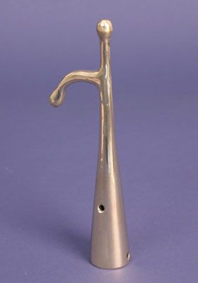
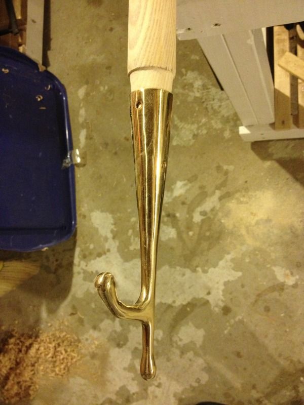
Here is the boat hook head, it comes from the WoodenBoat Magazine Store:


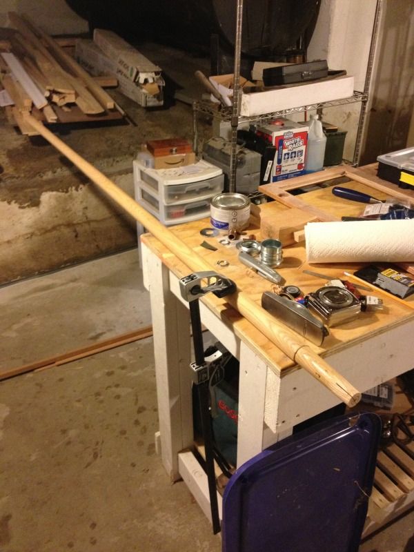
Here is the ash handle I bought way back when. You can see that the end that originally took the shovel head was too long and has been cut down and also is not steep enough of an angle to fit the boat hook casting.


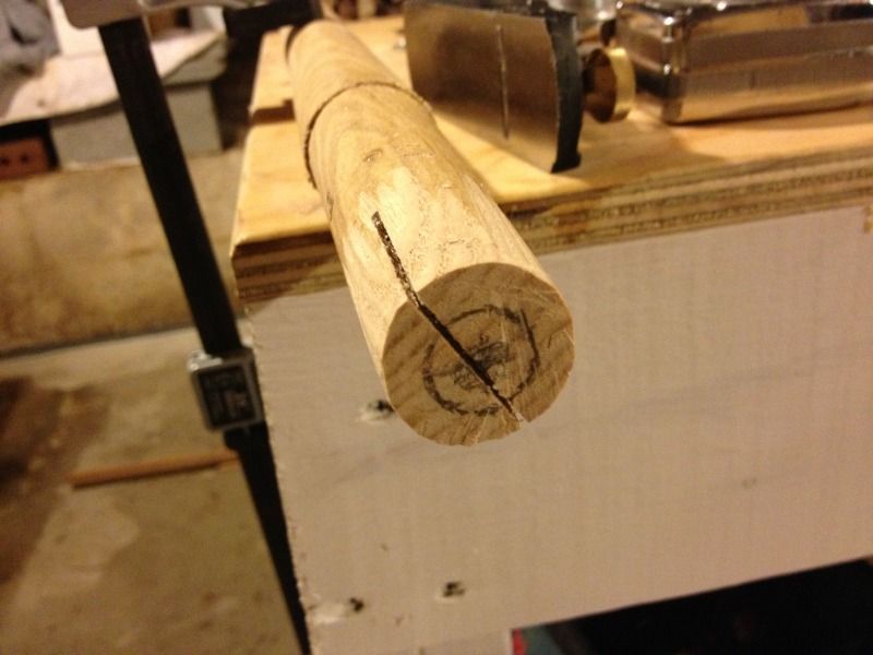
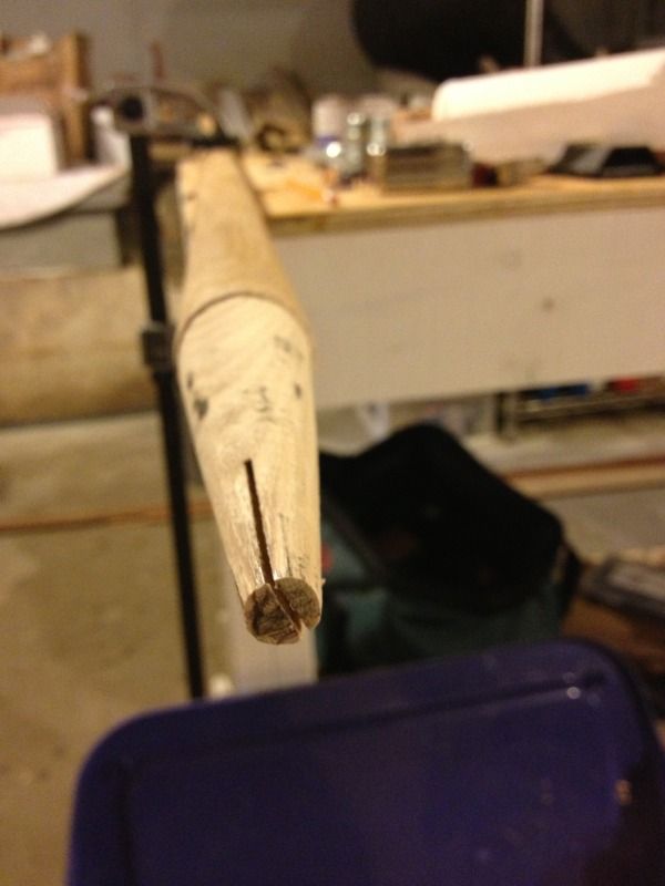
Here I have already started to take some passes with a block plane, but it's pretty close to the original diameter. The center is marked on the end as are a couple of concentric circles to give me a gauge as I start cutting it down to keep it centered.


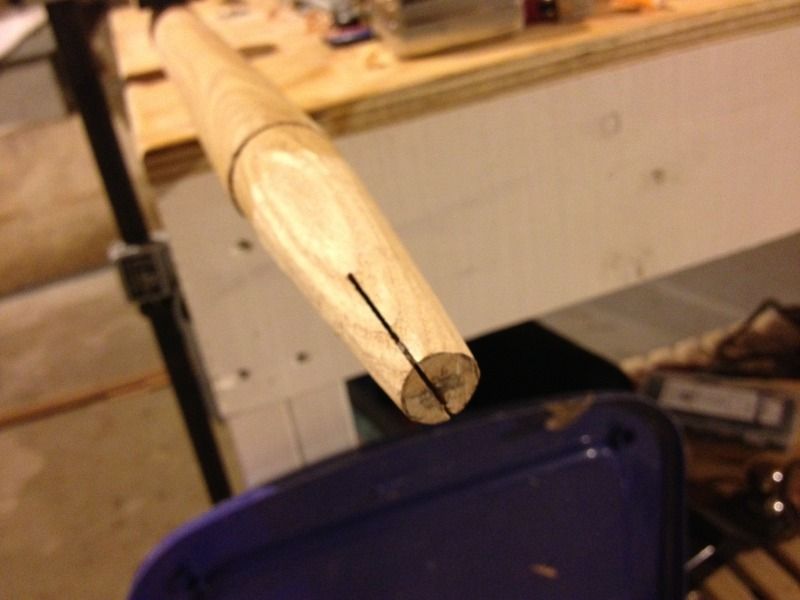
Down to the first circle, getting closer to the existing shoulder which is where the top of the boat hook casting will sit eventually.


Getting closer... The dark spots are from running a pencil on the inside of the casting before test fitting, gives you a sense of where it's touching. The inside of the casting isn't uniform and the closer it fits the stronger it will be.

Now we're getting pretty close. Taking down the high spots moves it up toward the shoulder about an 1/8th of an inch.


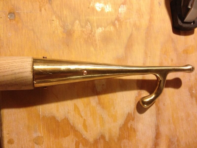
Next the holes are drilled from each side and lengths of 3/16 copper rod are cut to fit each hole so that an 1/8th of an inch or so is sticking out. The corners are beveled to make it slightly self aligning and then hammered into the holes to form the rivets. You could use screws, but rivets are stronger, look better, and are just saltier all around. Also they are really easy to do.


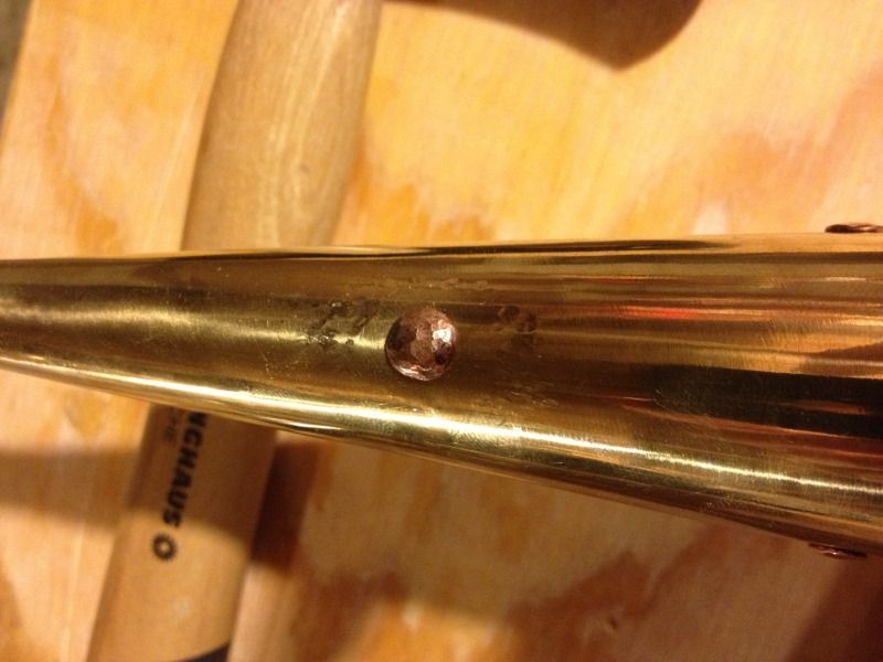
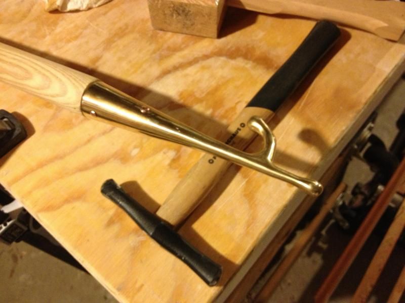
Here is one of the ends of the copper bar peened over. All it takes are light taps, I'm using a small blacksmithing hammer. The circle of divets around the rivet head are where the rounded head of the hammer is sliding down he side of the rivet head and hitting the boat hook. This is hammer movement is what gives it a domed shape and is the sign that it was done by hand.


And here it is  with all four rivets peened over resting on the small planishing hammer I used to form the rivets.


Now I need to shape and sand the rest of the handle, apply a few coats of varnish and put some fancy ropework on it and it will be ready for a few decades (hopefully) of service.

Monday, July 15, 2013

Welcome to the new blog

I'm happy to announce that I am consolidating  all of my project blogs and forum threads into this one ongoing blog. Now you can follow my progress or brows the documentation on all of my various  projects - past, present, and future - in one spot on the web.

Looking forward to posting some new updates soon!


Saturday, February 2, 2013

Back to Work!

Alrighty Folks,

Finally sucked it up and got back to work on the Hitia. Its a little bit tight in the garage space, but with the help of my latest recruit, Tyler, we were able to keep working on the front beam and paint the inside of the second hull.

Here's a picture of the beam as it sits right now:


And here is one of the inside of the second painted hull:


We left some unpainted space for the floors and for the eventual installation of the hatches. I was hoping to be able to start working on glassing the outside rather than painting, but it was too cold to work with that much epoxy and I didn't want to do a sloppy job with the fiberglass cloth. So I opted to paint the hull instead, and set up the flood lights and the radiator next to the beam to help it cure up. Then I got out of there because the paint fumes were giving me a headache.

After lunch I came back and was especially glad I didn't glass the hull. I had over done it with the heaters and lamps and blew out the power. I couldn't get in to the room housing the fuse box, so I had to leave the beam as she was. Hopefully that quick hardener works in those low temperatures as advertised!

If anyone has any experience working with epoxy in low temperatures (about 40 degrees F) I'd appreciate any tips.

Anyway, its a bit ghetto, but I'm glad to be back at work on the Hitia. Hopefully the groundhog was right and we're headed for an early spring and some warmer days!

Wednesday, December 12, 2012

The move to Jersey

Finally, I have the boat moved. I've ordered some clamps and a few other things and now I'm just waiting on some electric wiring to be completed in the garage and I'll be underway.

Back in CT the boat was looking particularly derelict. Here is a photo of the sorry state I found her in.


Here's another of the Hitia loaded on to the back of a dump truck. $30 toll fee going over the GW bridge!


Once the wiring is complete and I can see, I've got a bit of sweeping and a lot of organizing to do then I'll be back at work on the boat once again. Thanks to Jim Osowicki for his help with loading and the use of his truck!

Monday, December 3, 2012

A Quick Update...

So I have secured some garage space over in Hackensack, NJ close to where I work. The space is about 19' x 12' so it should accommodate the boat, tools and whatever else I'll need. It might get a little tight once I'm all set up, but if I can work in Kevin's basement, then this should be a breeze!

Kevin and I got together over Thanksgiving weekend to talk about the future of the boat. He has agreed to take on the remainder of the mast work, tiller arms, and maybe some of the cleats and other small stuff. I'm hoping to have the boat moved in by this weekend, but if I can't borrow a truck, at the very least I'll have the beams and epoxy and whatever else I can stuff into the back of my Jetta.

Photos and more to come!

Monday, November 26, 2012

Floor Installation

Following the move, Kevin and I both realized the incredible determent of having the boat stored halfway between Boston and New York City. With that in mind, and having the overwhelming itch to keep going and finish that which we have started, I began looking into storing the boat locally, in New Jersey, where I'll be able to get to it during the week and make more progress.

Without the use of Kevin's tools and space, and awesome clamps, I'll be moving forward with a limited set of tools and equipment (and experience). I'll be making most of the posts from here on out. Just gonna take small nibbles out of the project and watch it evolve, one step at a time. 

Here is a picture of the partially completed floor installation:


The jugs and varnish are there to add weight and help seal down the floor. I used a compass to trace the holes and cut out the circles using a jig saw. This will be finished up with a layer of fiberglass for added strength. 

The other hull still needs its final side of glass, below deck painting and floor installation. After that I'll be finishing the up the beams and sealing the hulls. 

Wish me luck!

Wednesday, August 8, 2012

Fiber glassing the hulls

Now that the hulls are assembled they won't fit back into the basement any more. It's been ok to keep them outside so far but the sunshine won't last forever so we are moving up the fiber glassing job to protect them while they are out in the weather.

The paint job looks a bit messy up on the saw horses but all those areas won't show.


All the stitches are out and the keel has been rounded over so we can put a piece of glass tape along the keel joint. This area is going to get the most abuse pulling the boat up on beaches so it gets a triple layering of fiberglass. The first layer is this tape and then the two side pieces will overlap over keel as well. We also put a bead of epoxy down to build up the radius and add more protection to the wooden keel strip.


Next we unrolled the 4oz fiberglass over the size of the hull and tacked it in place some epoxy where we couldn't hold it with tape.


Then we finally got down to spreading on the epoxy. We had been dreading the fiber glassing job and what would happen if we messed it up but it really wasn't that bad.


The fiberglass cloth does want to wrinkle as it laps over the curved edge of the keel but we kept at it and got all the wrinkles spread out.


The fiberglass also wraps up onto the skeg  and smooths out the transition. This area is probably going to require some filler and sanding later but is looking pretty good.


We also had to notch the cloth around the lash pad supports. We ended up just glassing down to the edge and trimming with a razor blade which made a pretty clean edge.


Then we just had to keep moving back between the two hull as each fiberglass job cured.


Sunday, July 29, 2012

Stem adjustments

The goal of every project is to learn from your mistakes - and so it is with this canoe build. It's time to laminate the aft stem and see if I'm any better at estimating the spring-back to get the right stem profile. By the time I get to the second canoe maybe I'll have the hang of it down.

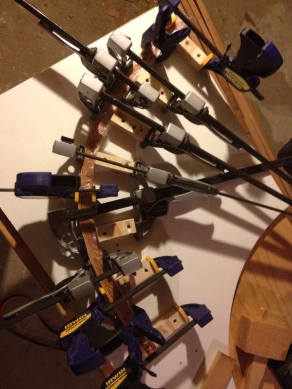
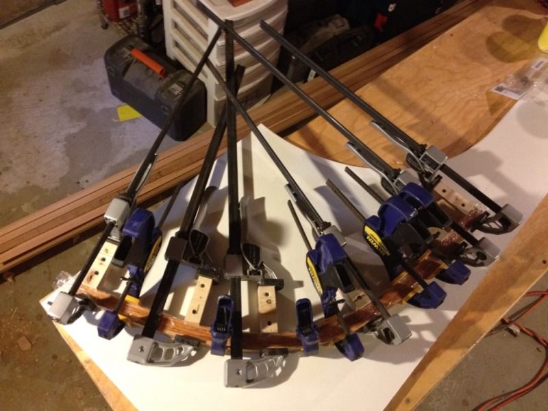
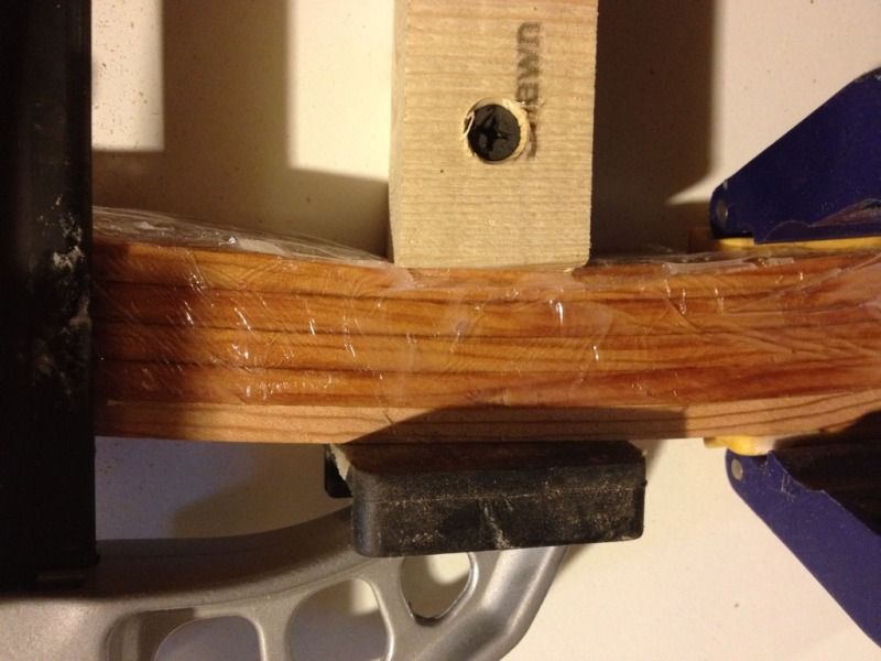
So on we go to gluing up the aft stem. I used more clamping points to better capture the curvature of the stem and also made sure to maintain the curvature through past the eventual end points. I still wish I had more clamps but it turned out fine and there were not gaps in the glue joints.


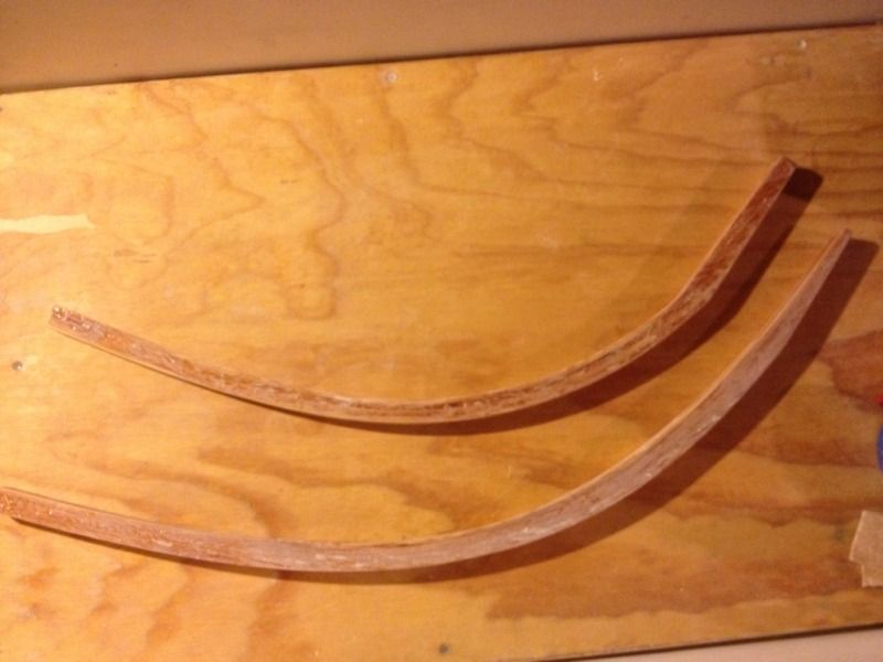
So what were the results you ask? Better, but not perfect. In the last installment the fore stem came out alright structurally but I overestimated the spring-back and that made the curve a bit too sharp. The aft stem is close, but the after moving it around to find the position that matches the drawn profile the best the area that connects to the keel is too short and will need to be lengthened. Mr. Oughtred draws such a beautiful boat it would be a shame to change the stem profile even slightly because of lamination errors so I'll be planing these stems down until they match the plans as perfectly as possible.


First up is the fore stem (the bottom one) and you can just barely see that at point of greatest deviation from the plans I had to take off almost a whole lamination layer thickness. This was then added back on the back side using a strip that was tapered on its ends to roughly match the amount removed. The result is a front face that matches the plans and fairly constant thickness. Almost like I did it right the first time!


Next it's time to adjust the aft stem. This one started much closer and only took a bit of cleaning up, but then it came time to beef up the too-short connection with the keel. It worked out that I could take the section that was cut off to from the bottom keel mating surface and glue it back on the top side of the stem. It looks a bit clunkier than the fore stem's keel connection but the aft end could use a bit of extra support since this joint carries the stresses from the rudder. I'll probably still taper it a bit more just so It's prettier to look at as every little detail counts in a small open boat like a canoe.


Well that's as far as I can get using the scraps that are laying around the shop so I'll have to actually invest in some materials soon to start building the strong-back and station molds that form the building jig.

Saturday, July 14, 2012

Let's get laminating

I decided to start with the MacGregor partly because it is the more versatile of the two canoes, but mostly because I already had 1" strips of Douglas fir lying around which is the right width for the MacGregor stems.

I marked the inboard edge of the stem on an old desk top by laying out the plans and using a sharp screw point every few inches. You can then take a pencil and darken each hole to make them easier to see. The strips on hand were a bit thicker than in the plans so I tried to leave a bit more allowance for spring back. I'm not sure how it's going to turn out but i'm hoping its close enough to be usable.


Each lamination is just under 1/4" thick which makes the four layers together about 7/8" thick, a bit short of the 1" target. I was thinking the epoxy in the joints would add some of that width back but they were pretty tight. I may be adding some more material to get the shape right once the stem is off the forms anyway, otherwise I'll consider it a bit of weight savings. The un-epoxied strip on the outside is to help keep the tension even along the outside strip, this seemed to help them make the bend easier.


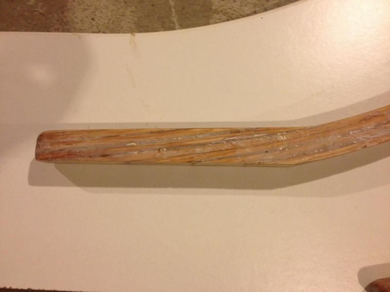
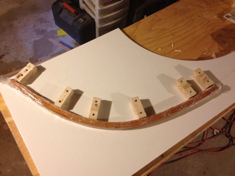
The next day the clamps come off and there is less spring back than I was expecting. That means I'm going to have to plane of some of the thickness in the middle section to get the shape just right and probably laminate another strip on to make it strong enough.


Here is the spring back near the keel - about 3/16".


Here is the spring back near the stem- about 1/4".


All in all a success, but I'm going to try and guess the spring back better for the aft stem and see what this one looks like once its planed down to match the plans exactly. The other thing I'm going to do differently is round the edges of the 2x4 pieces so that the corners aren't pressed into the inside face of the stem.